Project Description
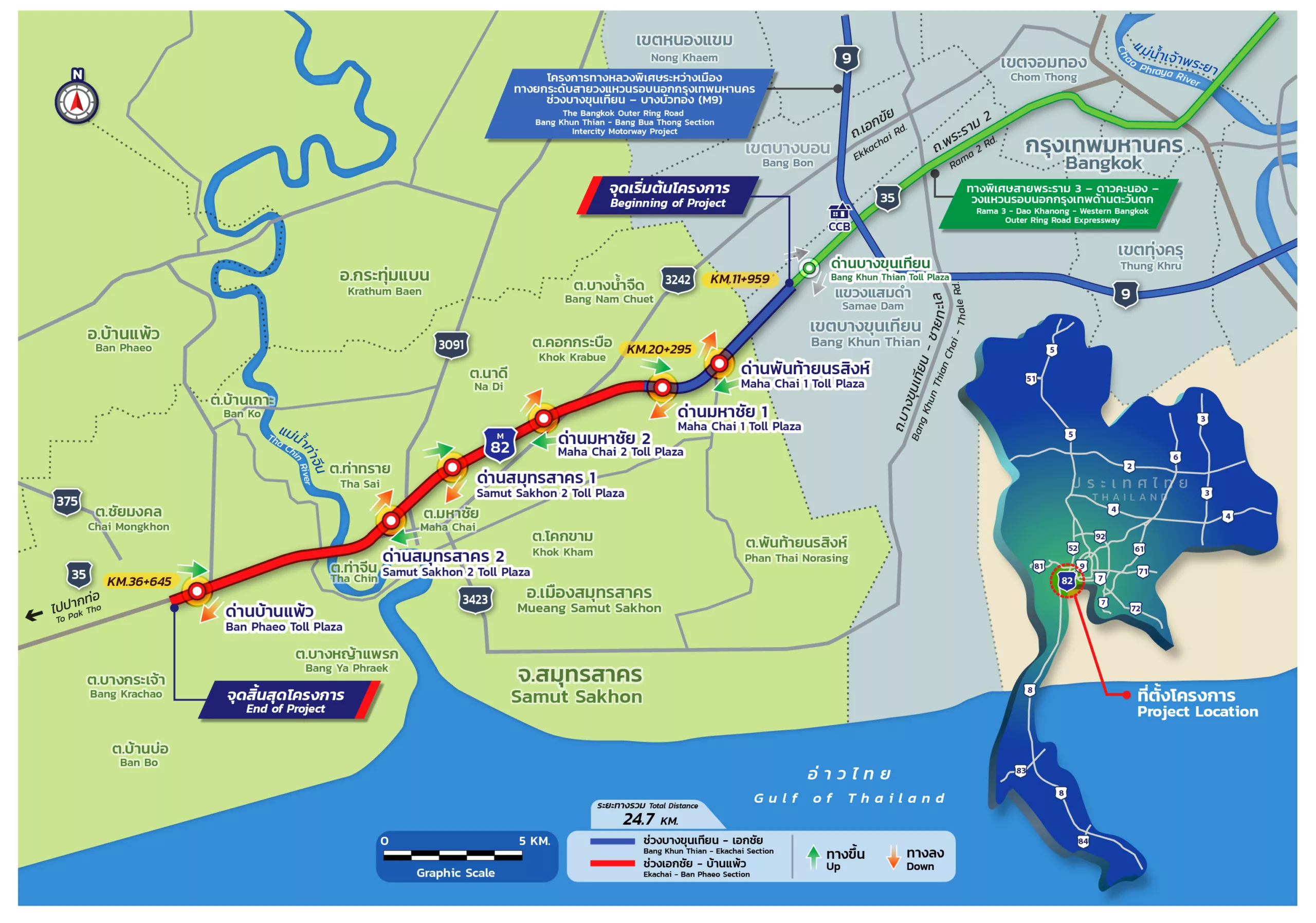
The project route is on Highway No. 35, starting from a point where it connects to the EXAT’s Rama III – Dao Khanong – Western Bangkok Outer Ring Expressway, at km. 11+959 of Highway No. 35 in Bang Khun Thian District, Bangkok, and terminating at km. 36+645 of the same highway in Ban Phaeo District, Samut Sakhon, covering 24.7 km. in total.
he 2-lane entrance and exit ramps are designed to function also as U-turn bridges.
A total of 6 toll gantries have been provided to accommodate the mobility between project alignments and other major road networks along the route, including:
- Phanthai Norasing Toll Gantry, located at km.16+125, is connected to Samae Dam Road;
- Mahachai 1 Toll Gantry, located at km.20+031, is connected to Highway No. 3242 (Ekachai Road);
- Mahachai 2 Toll Gantry, located at km.25+100, is connected to Highway No. 3242 (Ekachai Road);
- Samut Sakhon 1 Toll Gantry, located at km.27+100, is connected to Highway No. 3091 (Sethakit Road);
- Samut Sakhon 2 Toll Gantry, located at km.29+625, is connected to Highway No. 3091 (Sethakit Road); and
- Ban Phaeo Toll Gantry, located at km.36+500, is connected to Highway No. 375, Ban Bo – Lam Luk Bua route.
The toll gantry located at a point where the project connects to the Rama III – Dao Khanong – Western Bangkok Outer Ring Expressway for a smooth and seamless riding experience.
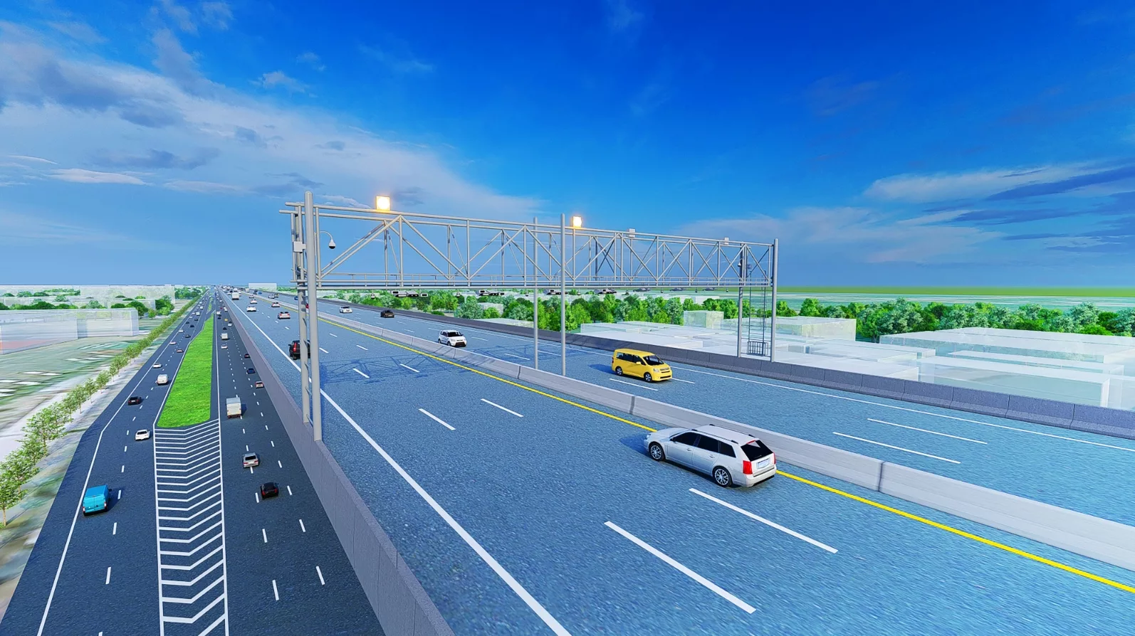
The project is designed to be a 6-lane elevated roadway, each of which is 3.60 meters’ wide, with 3 lanes in each direction. The traffic is divided by a 0.60-meter-wide concrete wall and the paved shoulders of 1.00 and 2.00 meters for the inner and outer respectively.
The closed toll system will charge motorway users for a distance-based fee via
M-Flow System, to allow a smooth and convenient driving without interruption.
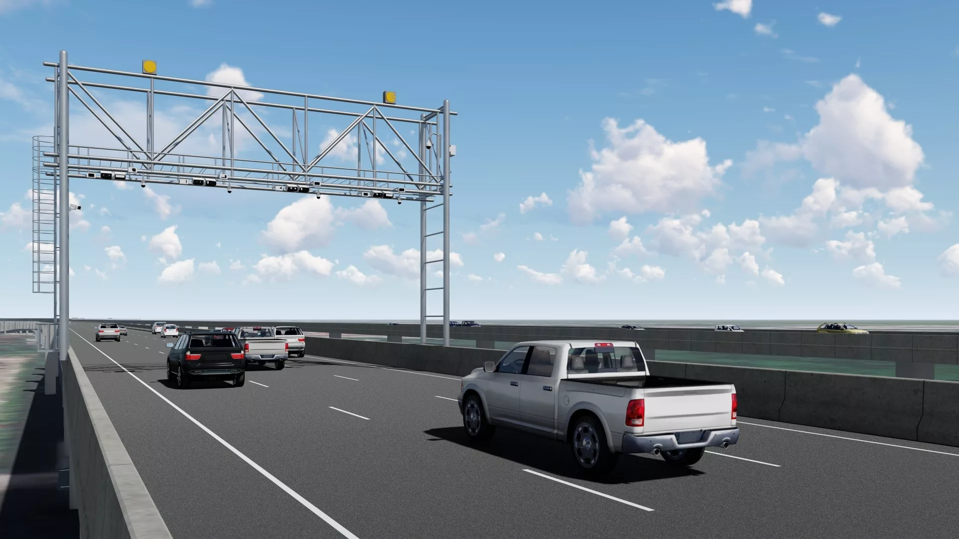
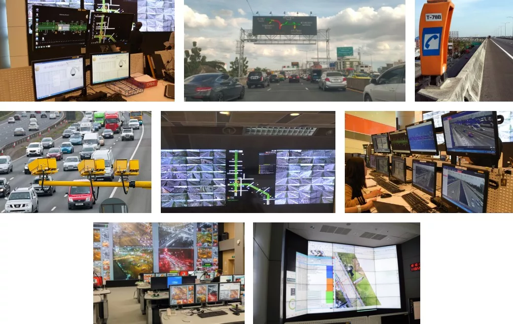
This system is designed to ensure safety and convenience for motorway users. In this regard, traffic-related commands will be made from the Central Control Building (CCB) and sent to different equipment along the project alignment, including:
- CCTV System
- Variable Message Sign (VMS)
- Emergency Telephone System (ETS)
- Automated Incident Detection System (AIDS)
- Automatic Traffic Detection System (ATID)
- Automated Speed Enforcement System (ASE)
- Data Communication Network System
- IP Telephone System
- Radio Communication
- Clock System
These consist of 2 main parts, namely, the design of lighting along the project alignment and the design of building services (E&M).
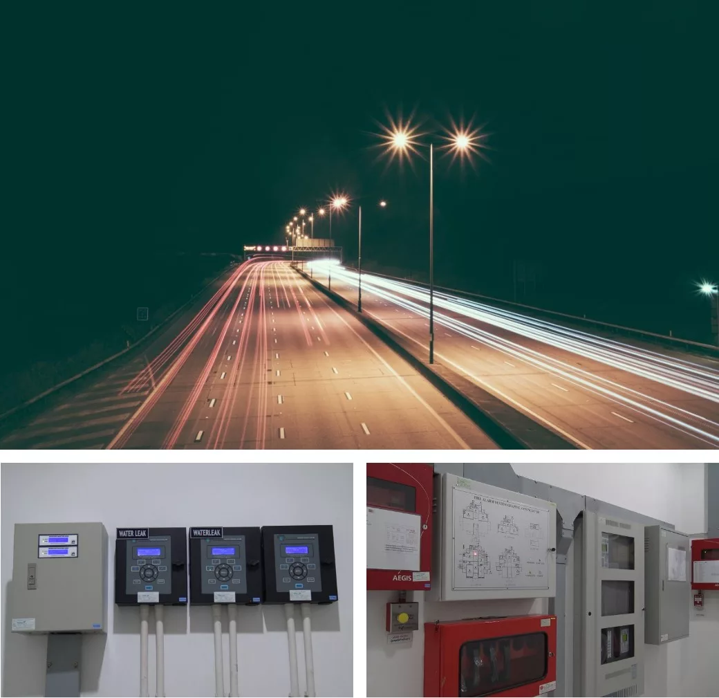
This system will supply power to Toll Collection System and the Central Control Building, to be further distributed to other equipment in the building. Sufficient numbers of generators and UPS shall be provided to allow for failure of the main power supply system.
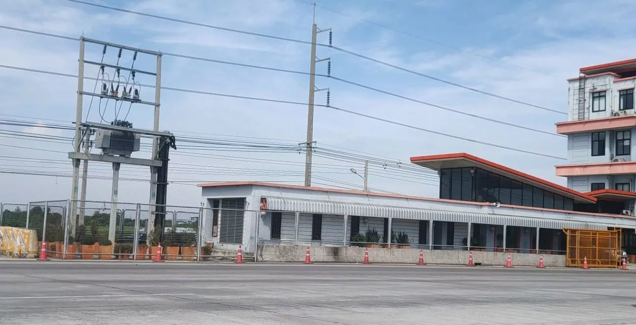
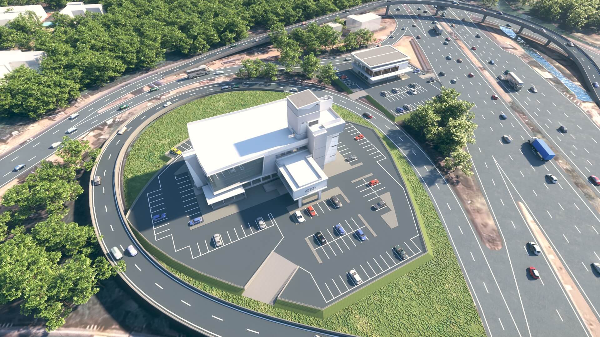
This is located at the area to be assigned by the DOH and serves as a traffic control center in managing traffic flow, facilitating motorway users as well as ensuring their safety and convenience.
- Central Control Building (CCB)
- Highway Police Division
- Operation and Maintenance Center
- Maintenance Workshop